|
|
|
|
|
|
|
|

| Disclaimer Information in this document is provided in connection with Intel products. No license, express or implied, by estoppel or otherwise, to any intellectual property rights is granted by this document. Except as provided in Intel's Terms and Conditions of Sale for such products, Intel assumes no liability whatsoever, and Intel disclaims any express or implied warranty, relating to sale and/or use of Intel products including liability or warranties relating to fitness for a particular purpose, merchantability, or infringement of any patent, copyright or other intellectual property right. Intel products are not intended for use in medical, life saving, or life sustaining applications. Intel may make changes to specifications and product descriptions at any time, without notice. Copyright © Intel Corporation (1996). Third-party brands and names are the property of their respective owners.
|
The Intel Architecture (IA) media extensions include single-instruction, multi-data (SIMD) instructions. This application note presents examples of code that exploit these instructions. Specifically, the MMxRowFilter function presented here illustrates how to use the new MMX technology unpack, multiply, and add instructions (PUNPCKLW, PUNPCKHW, PMULLW, and PADDW) to apply a filter across the rows of a graphical or video bitmap image. The MMxRowFilter code uses a seven tap filter whose coefficients sum to 256.
The MMX code performance improvement relative to traditional IA code is due to the ability to perform multiplication and addition of 16-bit values in parallel. The equivalent IA instructions IMUL and ADD would take 10 clocks and two clocks respectively. Additionally, the MMX instructions operate on packed 64-bit values which allows four 16-bit words to be multiplied and added in parallel.
The filtering function is defined by the following set of equations:
Two-dimension Function:  x(i,j) represented by a 32 bit field
                         |(i,j)|rx(i,j)|gx(i,j)|bx(i,j)|
where each of the elements is 8 bits long
	Row Filter Coefficient:	h(j)
	Filter Length:			L
	Row Filter Output:		y(i,j) represented by
                       |(i,j)|ry(i,j)|gy(i,j)|by(i,j)|
		where
                                 L-1
               y(i,j)=   x(i,j+n)h(n)
			                                 n=0
			                                 L-1
							ry(i,j)=   rx(i,j+n)h(n)
			                                 n=0
			                                 L-1
		 					gy(i,j)=   gx(i,j+n)h(n)
			                                 n=0
			                                 L-1
		 					by(i,j)=   bx(i,j+n)h(n)
			                                 n=0
The MMX row filter algorithm consists of two sections:
The decision to implement MMxRowFilter as two separate loops was made to illustrate the parallelism that can be obtained with the MMX instructions by unrolling different types of loops. An implementation which unpacks two pixels then filters them using one loop was considered. In this case, there was no advantage to doing so, since to calculate the filtered value for Pixel[n], you need to have access to Pixels[n + L], where L is the filter length. This would require unpacking those pixels, so there is no net advantage.
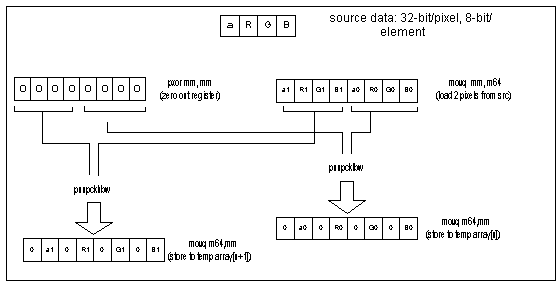
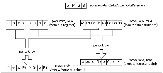
Data in the source bitmap is stored as 32-bits per pixel with 8-bit elements for , R, G, and B. Since the PMULL instruction operates on packed 16-bit words, we must unpack the data into 64-bit pixels composed of 16-bit elements. Arranging the data in this manner allows us to process in parallel the data for the PMULLW and PADDW instructions in the filter loop. Figure 1 illustrates the fundamental building block of the unpack loop.

The unpack loop consists of three of the building blocks illustrated in Figure 1. Each building block consumes two registers, (the register containing zeros is preserved). The loop is unrolled such that 6 pixels are unpacked for each iteration of the loop. Data alignment is critical here. Care was taken to align the source buffer on an 8-byte boundary. This is easily done in the C code by allocating buffer on the heap or global space and using compile switches to specify data alignment. One of the alternatives explored was to add three more layers of successive unpacking to yield like pixel components in each register, i.e.:
Unpacking the data in this manner would have allowed us to use the PMADDW instruction in the filter loop thus combining the multiply-accumulate into a single three cycle instruction. This method was discarded due to the number of additional cycles required to further unpack the data to that level.
pxor	mm0, mm0 			; Initialize unpack register to zero
unpack:
	movq		mm1,[eax]	; get first two pixels, MSW = PIXn+1 :: LSW = PIXn

	movq	    	mm3,8[eax]	; get next two pixels, MSW = PIXn+3 :: LSW = PIXn+2
	movq	    	mm2, mm1	; duplicate first two pixels

	punpcklbw	mm1, mm0	; expand PIXn's bytes to 16-bit words
	movq	    	mm4, mm3  	; duplicate next two pixels
	movq	    	mm5,16[eax]	; get next two pixels, MSW = PIXn+5 :: LSW = PIXn+4
	punpckhbw	mm2, mm0    	; expand PIXn+1's bytes to words
	movq		mm4, mm3	; duplicate first two pixels
	punpcklbw	mm3, mm0	; expand PIXn+2's bytes to 16-bit words
	movq        	0[ecx], mm1 	; PIXn to memory
	punpckhbw   	mm4, mm0	; expand PIXn+3's bytes to 16-bit words
	movq        	8[ecx], mm2 	; PIXn+1 to memory
	movq  		mm6, mm5	; duplicate next two pixels
    	movq   	16[ecx], mm3	; PIXn+2 to memory
	punpcklbw   	mm5, mm0	; expand PIXn+4's bytes to 16-bit words
  	movq       	24[ecx], mm4 	; PIXn+3 to memory
    	punpckhbw 	mm6, mm0    	; expand PIXn+5's bytes to 16-bit words
    	movq    	32[ecx], mm5	; PIXn+4 to memory
    	movq    	40[ecx], mm6	; PIXn+5 to memory
	add      	ecx, 48   	; increment temp array by 6 pixels
	add      	eax, 24	; increment src array pointer by 6 pixels (n+=6)
	sub      	ebx, 24	;  Decrement loop counter, don't split these two instr.
	jnz      	unpack
By far, the real work of the algorithm is done in this section. The selection of MMX instructions was predicated by data setup. As mentioned in Section 2.1, the decision to use discrete-multiply-and-accumulate instructions (PMULLW and PADDW) instead of the combined version (PMADDW) is driven by the need to conserve cycles in the unpack loop. The penalty for discrete-multiply-accumulate is one additional clock cycle for the PADDW. However, if care is taken to pair instructions in the Pentium® processor U and V pipes, this additional clock is not seen.
The filter coefficients are represented as 8-bit unsigned fixed-point. Since each pixel element was originally an 8-bit unsigned value, multiplying filter coefficients by pixel elements (R, G, B,and ) yields a 16-bit signed result, with the most significant 8-bits representing the whole part and the least significant eightbits representing the fractional part of the result.

Note that PMULLW is a 16-bit multiply which produces a 32-bit result. Since the pixel color values and filter coefficients were originally 8-bit values, the result of the multiply will contain at most 16 bits. Of this result, only the upper eight bits, or whole part, are significant. This is NOT the case if coefficients are greater that eight bits; this scenario is discussed in the next sections.
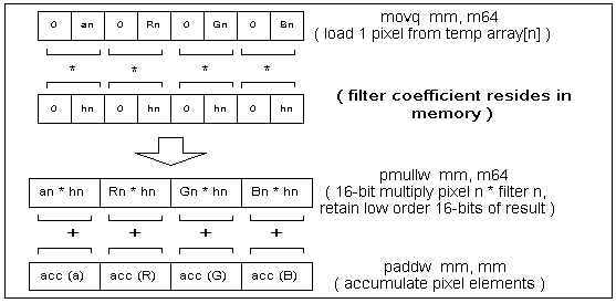
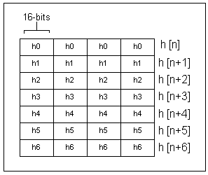
The basic building block of the filter loop is the multiply-accumulate (MACC) operation. We cannot use the single PMADDW instruction for MACC since we do not have like elements in the temp array. This same situation also requires that we arrange the filter coefficients in memory accordingly, as illustrated in Figures 3 and 4.


In the code example provided with this application note, we chose a fairly simple set of coefficients to give a straightforward example in instruction pairing and loop unrolling. Typically, however, filter coefficients will NOT be limited to 8-bit fixed-point representation. Let's look at an example where the coefficient require 13 bits of precision. In this case the data representation is shown in Figure 5.

A multiply result greater than 16 bits makes the use of the discrete MACC instructions (PMULLW and PADDW) not efficient since an additional multiply would be required to obtain the high order 16 bits of the result ( PMULHW ). Additionally, one still needs to combine the 16-bit results for accumulation and this is prohibitively costly in terms of CPU cycles. Some possible alternatives:
In the sample code provided with this application note, the number of taps in the filter (filter length) is seven and the code is optimized with this in mind. Realistically this can be any number. To implement a more general case, the developer should consider an inner-loop to implement the filter. The decision of whether to use an inner loop or not depends on the following considerations:
Since the core of the filter operation is relatively straightforward, the trick in implementing an MMX technology version is to take advantage of the parallelism of the instructions, pairing instructions between the U and V pipes and the pipeline multiply instruction. A method useful in identifying optimal pairing scenarios is to use a software pipelining diagram. For purposes of this application note, I'll define software pipelining as: interleaving more than one iteration of an algorithm in order to satisfy the latency and pairing rules as optimally as possible. To use a software pipelining diagram do the following steps:
	load:			movq		mm, mem64	=	L
	multiply:		pmullw		mm, mem64	=	M
	accumulate:		paddw 		mm, mm		=	A
For this algorithm, all instructions containing memory accesses were entered first, since static pairing rules dictate that memory accesses can only happen once per clock cycle and must always occur in the U pipe. Empty rows were then used to identify pairing opportunities for other instructions.
Table 1 shows the final pipelining diagram for one iteration of the filter loop. In this diagram each column contains the operations performed for each combination of hn and Pn that must be multiplied-acculumlated. Additionally, each U and V row pair represents one CPU clock. With this layout, one can easily lay out the algorithm taking into account the static pairing rules.
|
| ||||||||||||||
| U | L0 | |||||||||||||
| V | I6 | |||||||||||||
| U | M0 | |||||||||||||
| V | D2,1 | |||||||||||||
| U | M1 | |||||||||||||
| V | I7 | |||||||||||||
| U | L3 | |||||||||||||
| V | ||||||||||||||
| U | M2 | |||||||||||||
| V | D4,3 | |||||||||||||
| U | M3 | |||||||||||||
| V | A6,0 | |||||||||||||
| U | M4 | |||||||||||||
| V | A7,1 | |||||||||||||
| U | L0 | |||||||||||||
| V | A6,2 | |||||||||||||
| U | L2 | |||||||||||||
| V | D1,0 | |||||||||||||
| U | M0 | |||||||||||||
| V | A7,3 | |||||||||||||
| U | M1 | |||||||||||||
| V | A6,4 | |||||||||||||
| U | ||||||||||||||
| V | ||||||||||||||
| U | D3,2 | |||||||||||||
| V | ||||||||||||||
| U | M2 | |||||||||||||
| V | A7,0 | |||||||||||||
| U | L4 | |||||||||||||
| V | A6,1 | |||||||||||||
| U | M3 | |||||||||||||
| V | D0,4 | |||||||||||||
Notes:
| U | M4 | |||||||||||||
| V | A7,2 | |||||||||||||
| U | L1 | |||||||||||||
| V | ||||||||||||||
| U | M0 | |||||||||||||
| V | D2,1 | |||||||||||||
| U | M1 | |||||||||||||
| V | A6,3 | |||||||||||||
| U | L3 | |||||||||||||
| V | A7,2 | |||||||||||||
| U | M2 | |||||||||||||
| V | A6,0 | |||||||||||||
| U | M3 | |||||||||||||
| V | A7,1 | |||||||||||||
| U | ||||||||||||||
| V | ||||||||||||||
| U | A6,2 | |||||||||||||
| V | A7,3 | |||||||||||||
| U | ||||||||||||||
| V | ||||||||||||||
| U | ||||||||||||||
| V | ||||||||||||||
| U | ||||||||||||||
| V | ||||||||||||||
Notes:
The loop is unrolled so that optimal pairing can be achieved when performing the MACCs. Examination of Table 1 yields the following general observations:
This implementation of row filter is memory bound. When using MMX instructions you are allowed one memory access per clock and that access is limited to the U pipe.
Example 3 shows a code fragment from the filter loop, specifically the first eight clock cycles. This illustrates the interleaving and instruction pairing. Once the cache is full (each line is 32-bytes), memory operations carry no fetch penalty. The performance is the same as using MMX registers as operands.
pixloop:
        movq  	mm0, [eax]      	; load PIXn
        pxor   	mm6, mm6       	; zero out the PIXn accumulator
        pmullw  	mm0, [ebx]      	; PIXn*Hn
        movq  	mm2, mm1        	; duplicate PIXn+1
        pmullw  	mm1, [ebx]      	; PIXn*Hn
        pxor  	mm7, mm7        	; zero out the PIXn+1 accumulator
        movq    	mm3, 16[eax]    	; load PIXn+2
        pmullw   	mm2, 8[ebx]     	; PIXn+1*Hn+1
        movq     	mm4, mm3        	; duplicate PIXn+2
        pmullw 	mm3, 8[ebx]     	; PIXn+2*Hn+1
        paddw   	mm6, mm0        	; accumulate Pn
        pmullw	mm4, 16[ebx]    	; PIXn+2*Hn+2
        paddw   	mm7, mm1        	; accumulate Pn+1
The code module supplied is not reentrant, however it can be made reentrant with a few minor modifications:
Due to loop unrolling, the current implementation places the following constraints on data sets:
Once the cache is filled, the unpack loop executes in an average of 92 clocks per loop. At six pixels per loop, we average 16 clocks/pixel for unpacking.
Once the cache is filled, the filter loop executes in an average of 45 clocks per loop. At two pixels per loop, we average 23 clocks/pixel for the filter.
The C code below is shown to illustrate the functionality of the row filter algorithm. It is not intended to match the implementation of the MMX technology version.
void CRowFilter( DWORD p[][IMAGE_WIDTH],
                 short *h,
                 DWORD q[][IMAGE_WIDTH],
                 short nRows,
                 short nCols, short hLength )
{
    short    r[IMAGE_HEIGHT][IMAGE_WIDTH];
    short    g[IMAGE_HEIGHT][IMAGE_WIDTH];
    short    b[IMAGE_HEIGHT][IMAGE_WIDTH];
    short    a[IMAGE_HEIGHT][IMAGE_WIDTH];
    DWORD A, R, G, B;
    short i, y, x;
for (y=0; y<nRows; y++)
    {
        for (x=0; x<nCols; x++)
        {
            b[y][x] = (short) (p[y][x]&0x000000ff);
            g[y][x] = (short) ((p[y][x]>>8)&0x000000ff);
            r[y][x] = (short) ((p[y][x]>>16)&0x0000ff);
            a[y][x] = (short) ((p[y][x]>>24)&0x0000ff);
        }
    }
    for (y = 0; y < nRows; y++)
    {
        for (x = 0; x < nCols-hLength; x++)
        {
            A=0;
            R=0;
            G=0;
            B=0;
            for ( i=0; i<hLength; i++)
            {
                A+= a[y][x+i]*h[i];
                R+= r[y][x+i]*h[i];
                G+= g[y][x+i]*h[i];
                B+= b[y][x+i]*h[i];
            }
			A=A+0x0080;
			R=R+0x0080;
			G=G+0x0080;
			B=B+0x0080;
			q[x] = ((A<<16)&0xff000000) |
				((R<<8)&0x00ff0000) | 							(G&0x0000ff00) |
				((B>>8)&0x000000ff);
        }
    }
//    __asm int 3
}   // eo row filter
.486P
.Model FLAT, C
IMAGE_WIDTH     EQU     72
IMAGE_HEIGHT    EQU     58
FILTER_LENGTH   EQU     7
_DATA	SEGMENT
	Arr16       DWORD   IMAGE_WIDTH*IMAGE_HEIGHT*2  DUP   (0)
	rnduparr    WORD    4                           DUP   (128)
	srcsize     DWORD    IMAGE_WIDTH*IMAGE_HEIGHT*4
	Arr16siz    DWORD    (IMAGE_WIDTH*IMAGE_HEIGHT*4*2)-64
	pixtemp     DWORD   0
_DATA	ENDS
_TEXT	SEGMENT PUBLIC USE32 'CODE'
MMxRowFilter PROC C PUBLIC USES ebx ecx edi esi, src:PTR DWORD,
                                                 filt:PTR SWORD,
                                                 dest:PTR DWORD,
                                                 temp:PTR DWORD
mov	eax, src			; Source bitmap pointer
mov	ebx, filt			; Filter pointer
mov	ecx, dest			; Destination bitmap pointer
mov	ebx, srcsize
mov	ecx, temp
pxor	mm0, mm0			; Initialize unpack register to zero
unpack:
	movq		mm1,[eax]	; get first two pixels, MSW = PIXn+1 :: LSW = PIXn

	movq		mm3,8[eax]	; get next two pixels, MSW = PIXn+3 :: LSW = PIXn+2
	movq		mm2, mm1	; duplicate first two pixels
	punpcklbw	mm1, mm0	; expand PIXn's bytes to 16-bit words
	movq		mm4, mm3	; duplicate next two pixels
	movq		mm5,16[eax]	; get next two pixels, MSW = PIXn+5 :: LSW = PIXn+4
	punpckhbw	mm2, mm0	; expand PIXn+1's bytes to words
	movq		mm4, mm3	; duplicate first two pixels
	punpcklbw	mm3, mm0	; expand PIXn+2's bytes to 16-bit words
	movq 		0[ecx], mm1	; PIXn to memory
	punpckhbw	mm4, mm0	; expand PIXn+3's bytes to 16-bit words
	movq		8[ecx], mm2	; PIXn+1 to memory
	movq		mm6, mm5	; duplicate next two pixels
	movq		16[ecx], mm3	; PIXn+2 to memory
	punpcklbw	mm5, mm0	; expand PIXn+4's bytes to 16-bit words
	movq		24[ecx], mm4	; PIXn+3 to memory
	punpckhbw	mm6, mm0	; expand PIXn+5's bytes to 16-bit words
	movq		32[ecx], mm5	; PIXn+4 to memory
	movq		40[ecx], mm6	; PIXn+5 to memory
	add		ecx, 48	; increment temp array by 6 pixels
	add		eax, 24	; increment src array pointer by 6 pixels (n+=6)
	sub		ebx, 24
	jnz	unpack
mov         eax, temp			; U-pipe: load address of temp array
mov         ebx, filt			; load address filter array[0][0]
mov         esi, dest

movq        mm5, DWORD PTR rnduparr	; load rounding constants (0x0080)
sub         esi, 8			; pre decrement dest array pointer for better
						; pairing inside the loop
mov         edx, Arr16siz
movq        mm1, 8[eax]             ; load PIXn+1
pixloop:
        movq        mm0, [eax]      ; load PIXn
        pxor        mm6, mm6        ; zero out the PIXn accumulator
        pmullw      mm0, [ebx]      ; PIXn*Hn
        movq        mm2, mm1        ; duplicate PIXn+1
        pmullw      mm1, [ebx]      ; PIXn*Hn
        pxor        mm7, mm7        ; zero out the PIXn+1 accumulator
        movq        mm3, 16[eax]    ; load PIXn+2
        pmullw      mm2, 8[ebx]     ; PIXn+1*Hn+1
        movq        mm4, mm3        ; duplicate PIXn+2
        pmullw      mm3, 8[ebx]     ; PIXn+2*Hn+1
        paddw       mm6, mm0        ; accumulate Pn
        pmullw      mm4, 16[ebx]    ; PIXn+2*Hn+2
        paddw       mm7, mm1        ; accumulate Pn+1
        movq        mm0, 24[eax]    ; load PIXn+3
        paddw       mm6, mm2        ; accumulate Pn
        movq        mm2, 32[eax]    ; load PIXn+4
        movq        mm1, mm0        ; duplicate PIXn+3
        pmullw      mm0, 16[ebx]    ; PIXn+3*Hn+2
        paddw       mm7, mm3        ; accumulate Pn+1
        pmullw      mm1, 24[ebx]    ; PIXn+3*Hn+3
        paddw       mm6, mm4        ; accumulate Pn
        movq        mm3, mm2        ; duplicate PIXn+4
        pmullw      mm2, 24[ebx]    ; PIXn+4*Hn+3
        paddw       mm7, mm0        ; accumulate Pn+1
        movq        mm4, 40[eax]  ; load PIXn+5
        paddw       mm6, mm1      ; accumulate Pn
        pmullw      mm3, 32[ebx]  ; PIXn+4*Hn+4
        movq        mm0, mm4      ; duplicate PIXn+5
        pmullw      mm4, 32[ebx]  ; PIXn+5*Hn+4
        paddw       mm7, mm2      ; accumulate Pn+1
        movq        mm1, 48[eax]  ; load PIXn+6
        pmullw      mm0, 40[ebx]  ; PIXn+5*Hn+5
        movq        mm2, mm1      ; duplicate PIXn+6
        pmullw      mm1, 40[ebx]  ; PIXn+6*Hn+5
        paddw       mm6, mm3      ; accumulate Pn
        movq        mm3, 56[eax]  ; load PIXn+7
        paddw       mm7, mm4      ; accumulate Pn+1
        pmullw      mm2, 48[ebx]  ; PIXn+6*Hn+6
        paddw       mm6, mm0      ; accumulate Pn
        pmullw      mm3, 48[ebx]  ; PIXn+7*Hn+6
        paddw       mm7, mm1      ; accumulate Pn+1
                                  ; one clock stall due to pmullw latency with mm2
        paddw       mm6, mm2      ; accumulate Pn

                                  ; one clock stall due to pmullw latency with mm3
        paddw       mm7, mm3      ; accumulate Pn+1
        paddw      mm6, mm5       ; PIXn : a=a+0x80, r=r+0x80, g=g+0x80, b=b+0x80,
        paddw      mm7, mm5       ; PIXn+1 : a=a+0x80, r=r+0x80, g=g+0x80, b=b+0x80,
        psrlw       mm6, 8        ; shift to obtain whole part of result
        add         esi, 8        ; increment destination pointer by 2 pixels
        psrlw       mm7, 8        ; shift to obtain whole part of result
        add         eax, 16       ; increment temp array pointer by  2 pixels
        packuswb    mm6, mm7      ; MSW = PIXn+1 :: LSW = PIXn

        movq        mm1, 8[eax]   ; load PIXn+1 for next iteration of loop
        movq        [esi], mm6    ; store to dest array
        sub         edx, 16
        jnz         pixloop
emms
ret
MMxRowFilter ENDP
_TEXT	ENDS
END